CAP Physics
Written by Drenchenator
Last updated on 2008-01-17
The Regulator

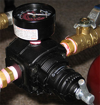
A constant air pressure system allows the consistency of CPS and the power of air pressure through one device: a pressure regulator. The regulator keeps the pressure in the firing chamber roughly the same, allowing for consistent performance in both output and range, keeping extra pressure in the source chamber.
The System

A CAP system operates with three distinct piece: a source chamber that serves as a pressurized air reservoir, a pressure regulator to keep the pressures the same, and a firing chamber. In this diagram, the source chamber is on the left; the firing chamber is on the right. The diagram is animated to agree with the following graph.
Definition of Variables
- Pressure
- P0 - the pressure to which the source chamber was filled
- PC - the pressure at which the regulator is set; the pressure that is maintained in the firing chamber
- PS - the pressure in the soruce chamber after a set amount of outflow
- PA - the pressure of the atmosphere, 1 atm or 14.7 psia.
- PF - the final pressure that the system is at after all of the water has left the system
- Volume
- VS - the total volume of the source chamber
- VC - the total volume of the firing chamber
- VT - the volume of water with which the firing chamber was filled
- VQ - the total amount of outflow; the amount of water that has left the system
Pressures

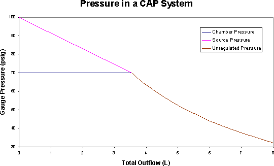
The above graph relates the outflow and pressure ideally. The system has these properties:
- There are 8L of water in the 10L firing chamber.
- The chamber pressure is set at 70 psig.
- The 10L source chamber begins at 100 psig.
The firing chamber's pressure hovers at its set value until the source chamber's pressure equals it; afterwards the pressures drops in both chambers at the same unregulated rate. The source chamber's pressure drops linearly according according to the following equation: (this equation required a lengthy derivation that I do not want to go into now)

Only a certain amount of outflow can occur before the source chamber's pressure is the same as the firing chamber's:

The intersection of the curves on the graph above occurs when this occurs: once this quantity of water has left the firing chamber, the pressure in both chambers remains the same, falling at the same rate.

After the discussed quantity of outflow the pressure drops ideally according to the above equation. This is represented by the curve beginning at about (3.5, 70) on the graph. This curve continues down until it reaches the point at which no water remains in the firing chamber, here at 8L of outflow; a final amount of pressure is given by the following equation:

However, we construct constant air pressure systems to keep the working pressure the same--without the same pressure our work is for nothing. What pressure should we fill the source chamber to provide this constant pressure through the entirety of the shot?

Considering all the needed quantities, this equation provides a working relationship to properly power a CAP system and sustain its advantages over conventional systems. And the equation makes sense--larger source chambers need less pressure, greater total flows neede more pressure.